Call us: 01268 561688
15 OBAN COURT HURRICANE WAY, WICKFORD ESSEX SS118YB
Opening Hours
Weekdays 9.00 - 17.30
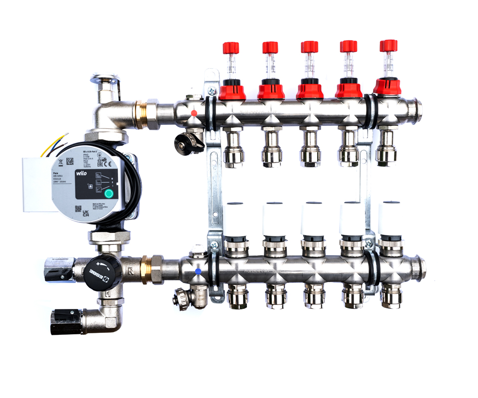
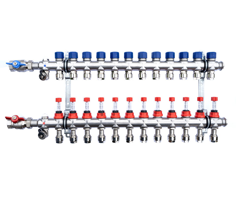
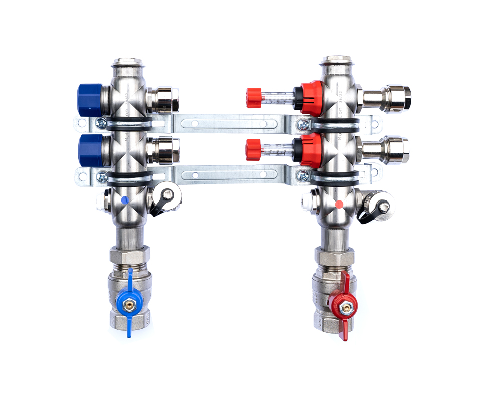
RADIANT FLOOR SOLUTIONS Distribution Manifold
Copyright Radiant © 2026. All rights reserved